Chapter 02 · Watch, then practise
Programming with 8085 Microprocessor
Watch the related lecture, then read the question and answer below.
10 questions · 14 playlist videos. Matches are based on video titles; broader background matches are labeled.
Watch the full playlist ↓Chapter playlist
Programming with 8085 Microprocessor
8085 | Architecture in HINDI | Bharat Acharya Education
Bharat Acharya Education · 1:34:02
Choose a video · 2 lectures
Architecture topic matches based on video titles; exact coverage of this question has not been verified.
1. 8085 programmer’s model
Explain briefly the programmer's model of 8085 microprocessor.
Answer
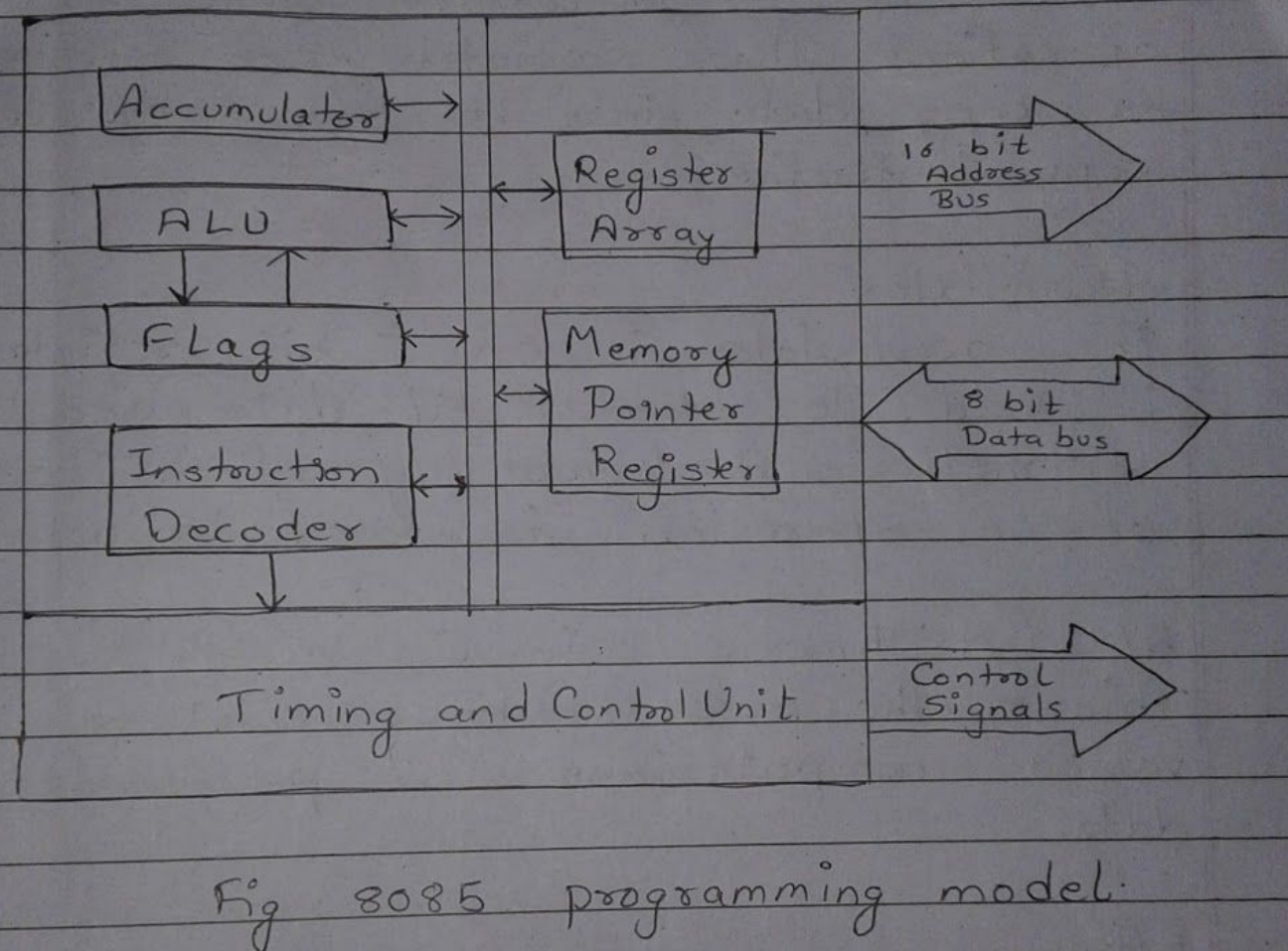
The programming model consists of some segments of the ALU and the registers. This model doesnot reflect the physical structure of 8085 but includes the information that is critical in writing the assembly language progra
Registers
8085 has six registers to store 8 bit data. They are identified as B, C, D, E, H & L. They can be combined as register pair BC, DE an HL - to perform some 16-bit operations. These registers are used to store or copy data into it by using data copy instructions.
Accumulator
The accumulator is an 8 bit register that is used to store 8 bit data and perform arithmetic and logical operation. The result of an operation is stored in accumulator.
ALU (Arithmetic Logic Unit)
This is the area of microprocessor where various computations are performed on data.
Flags
The ALU includes five flipflops, which are set or reset after an operation according to data conditions of results in the accumulator. They are Zero (Z), Carry (CY), Sign (S), Parity (P) and Auxiliary Carry (AC) flags. The microprocessor uses these flags to test data conditions. These flags have critical importance in decision making process in the microprocessor.
Memory Pointers
It is also called as stack pointer. It points to a memory location in R/W memory called as stack
Program Counter register
The microprocessor uses the PC register to sequence the execution of the instruction. i.e. it points to the memory address from which the next byte is to be fetched.
Timing and Control Unit
It provides necessary clock pulses to all the components and controls in the operation.
16-bit Address Bus
It is used to carry 16-bit address of pheripheral or memory locations.
8 bit Data Bus
It is used to transfer binary informations.
8085 Microprocessor Architecture Bharat Acharya Engineering, GATE Studies
Bharat Acharya Education · 40:46
Choose a video · 2 lectures
Topic matches: 8085 architecture and its block diagram. Exact question coverage has not been verified.
2. Internal block diagram of 8085
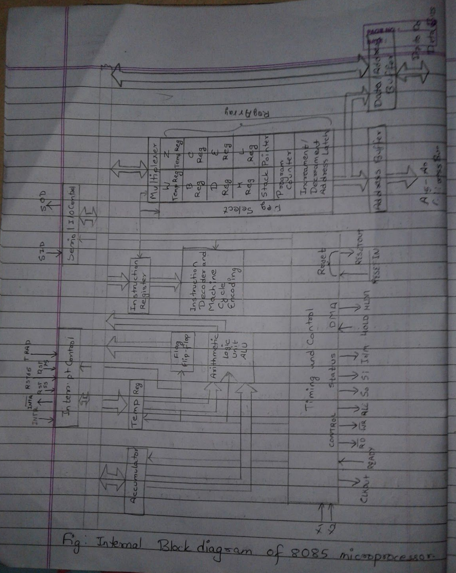
Draw the internal block diagram of the 8085 microprocessor? Explain each part in brief.
Answer
Accumulator
The accumulator is an 8 bit register that is used to store 8 bit data and perform arithmetic and logical operations. When the data is read from input, it is first moved to accumulator. When the data is output, it is first placed in the accumulator.
Temporary Register
The temporary register is an 8 bit register not accessible to the programmer. While executing the instruction the 8085 A often places the data into temporary register
Instruction Register
The instruction register receives the operation code of instructions from the internal data bus and passes it to the instruction decoder and machine cycle encoder circuit.
Instruction decoder and Machine cycle encoder
The instruction register is not directly accessible to the programmer. The instruction decoder decodes the op-code so that the microprocessor knows what type of operation is to be performed before executing it.
Register Array
8085 has six registers to store 8 bit data. They are identified as B, C, D, E, H & L. They can be combined as registers pairs BC, DE and HL - to perform some 16-bit operations. These registers are used to store or copy data into it by using data copy instructions. In addition, registers H & L are utilized to in indirect addressing mode. In this mode, the memory location whose address is specified by the content of the register.
Stack Pointer
A stack is an area of memory set aside for the purpose of storing data, by an operation known as stacking. As data is stored and retrieve, its location is specified by a 16-bit register known as stack pointer.
Program Counter
As the 8085 A begins to execute an instruction the memory address of the first instruction to be executed is placed in the register called program counter.
ALU (Arithmetic Logic Unit)
This is the area of microprocessor where various computations are performed on data.
Flags
The ALU includes five flipflops, which are set or reset after an operation, according to data conditions of result in accumulator. They are zero (Z), Carry (CY), Sign (S), Parity (P) and Auxiliary Carry (AC).
Timing and Control
It provides necessary clock pulses to all the components and controls in the operation.
Interrupt Control
An interrupt is an asynchronous process of communication with the microprocessor, initiated by an external pheripheral. It is controlled by interrupt control.
Data transfer from source to destination
AAkrit Subedi · 3:27
Choose a video · 3 lectures
Related examples of data transfer, addition, and subtraction. The playlist does not separately identify every instruction group in this question.
3. 8085 instruction classification
In how many ways Intel 8085 Instruction set can be classified? Explain with examples.
Answer
The Intel 8085 Instruction set can be classified into 5 categories
- Data Transfer Group
- Arithmetic Group
- Logical Group
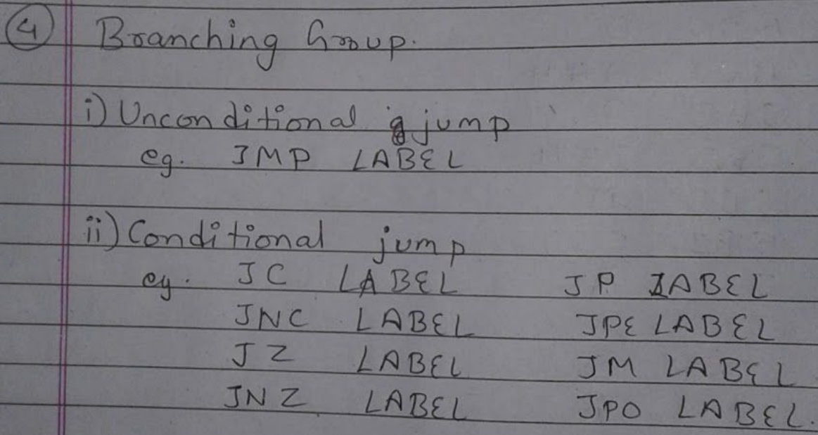
- Branching Group
- Miscellaneous Group.
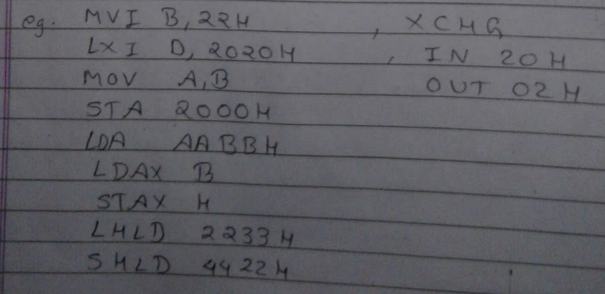
Data Transfer Group
These are used to transfer data to register, memory or accumulator.
No flags are affected in data transfer group
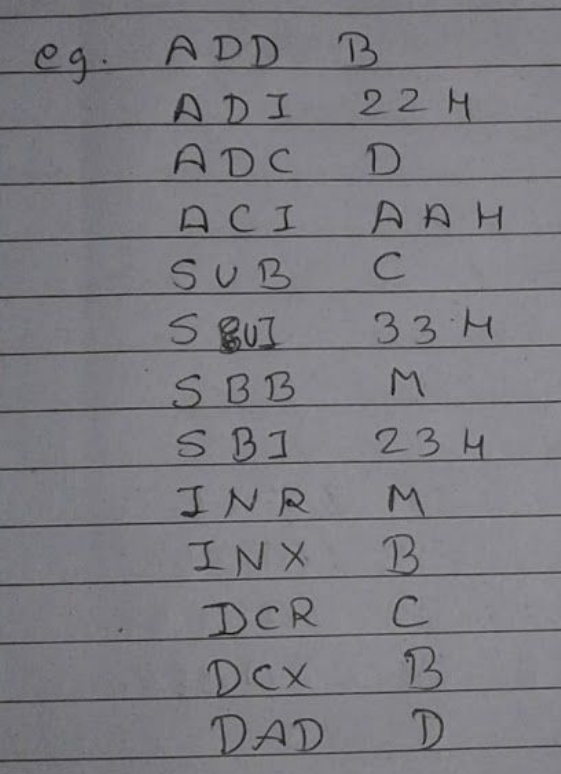
Arithmetic Group
These are used to perform arithmetic operations on the accumulator.
All flags are affected in arithmetic group
Logical Group
These are used to perform logical operations on the accumulator.
All flags are affected in logical group
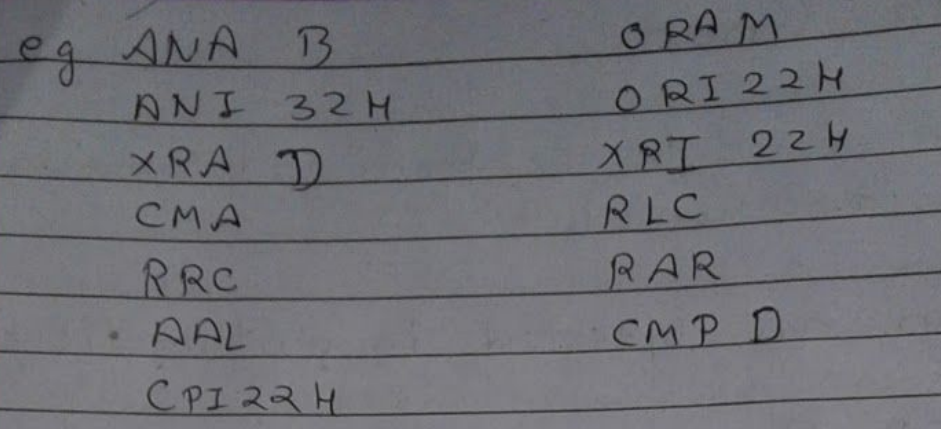
Miscellaneous Group.
No dedicated CALL/RET/PUSH/POP or program-counter/stack-pointer lecture is identified by the supplied chapter video titles.
4. Program counter and stack pointer
What is the use of Program Counter and Stack pointer registers of 8085 microprocessor? How these registers get affected during CALL, RET, PUSH and POP instructions explain with suitable examples.
Answer
The program Counter stores the 16 bit Address data. The program counter stores the address of the memory that is to be executed next. So the microprocessor uses this register to sequences the execution of instructions. Depending upon the instruction type the program counter is incremented by one, two or three to point to the next memory location. Its value cannot be changed by the user
The Stack Pointer is the 16 bit register that stores the location of the bottom top of the stack. Its value decreases as the Push operation is done.
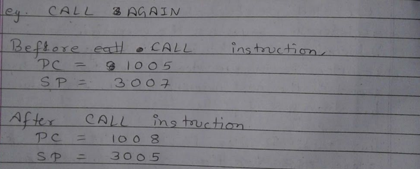
When CALL instruction is used, the Program counter is increased by 3 as the CALL instruction is 3 byte instruction.
And the address of next instruction is stored on the stack i.e. the stack pointer register is decreased by 2.
When RET instruction is used
Program Counter is increased by 1 as it is 1 byte instruction.
And the 2 byte from top of stack is transfered to program counter and program counter is changed to the data of stack.
And SP is decreased by 2 increased by 2

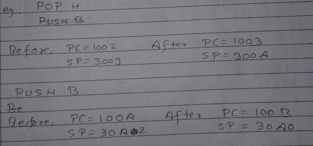
When PUSH or POP instruction is used, the PC is increased by 1 as it is 1 byte instruction
And, the stack pointer increases by 2 when POP is done and decreases by 2 when PUSH is done.
Addition in Microprocessor 8085
AAkrit Subedi · 1:54
Related addition example only; the title does not establish coverage of all flags or these exact programs.
5. 8085 flags
What is flag? Discuss about 8085 associated flags. Along with suitable examples show how these flags are affected by arithmetic and logical group of instructions.
Answer
Flags.
Registers containing of five flipflops, each holding status of different states separately is known as Flag Registers and each flip flops are called flags.
In the process of performing arithmetic and logic operations, the 8085 A can set or reset one or more of the flag.
The 8085 associated flags are:
Carry flag
Sets when Accumulator exceeds 8 bit
Zero
Sets when Accumulator is 00H
Sign
Sets when MSB of Accumulator (i.e D₇) is 1
Parity
Sets when the content of Accumulator contain even no of 1.
Auxiliary Carry
Set when D₃ generates carry.
For the program below:
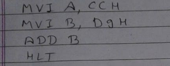
Here the addition between CC & D9 is performed i.e.
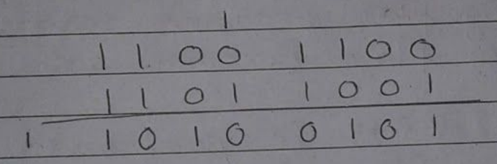
Carry flag is set because The sum exceeds 8 bit.
Sign becomes set as MSB is 1.
Parity is also set because the sum has four 1.
Auxiliary Carry is also set as D₃ generates a carry.
Zero is reset
For program below:
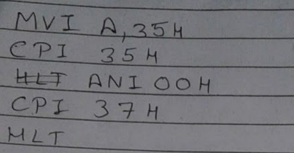
Here the data in Accumulator is 35H. So when CPI 35H is performed, the carry flag becomes reset and zero flag becomes set.
When CPI 37H is performed, the carry flag becomes set and zero flag becomes reset.
When ANI 00H is performed the Auxiliary Carry flag is set Carry flag is reset and Zero flag is set.
Instructions format || microprocessor || in Hindi || by Informationduniya
Information Duniya · 8:46
Topic match: instruction format. The title does not verify coverage of the source’s data formats or opcode-design explanation.
6. Instructions, opcodes, and data format
What do you mean by instructions? Explain how instruction and opcodes are designed in microprocessor. Describe about data format used in microprocessor.
Answer
Instructions.
An instruction is a command to the microprocessor to perform a given task on specified data.
Each instructions have two parts
- Operation code
- Operands.

The memory of the microprocessor consists of various memory locations called words of 40 binary digits each. Both data and instructions are stored there. Here numbers must be represented in binary form, each instructions also has to be in binary code. A word may also contain two 20-bit instruction with each instructions consisting of an 8 bit op code, specifying the operation to be performed and a 12 bit address designating one of the word in the memory. So the instructions consists of mainly two fields op-code and the address. The opcond determines which operation is to be performed.
The data format used in microprocessor are explained as:-
i) ASCII code
7 bit alphanumeric code that represents decimal numbers, alphabets and non-pointable characters
ii) BCD code
Decimal bit from 0 to 9 are represented by 4 binary bits and (A-F) are invalid.
iii) Signed integers
Either positive or negative
D₇ of 8 bit number is specified as sign.
iv) Unsigned integer
All integer without a sign can be represented by the 8 bit in a microprocessor register.
8085 addressing modes | COA | Lec-73 | Bhanu Priya
Education 4u · 16:16
Topic match: 8085 addressing modes; the exact handwritten examples have not been verified against the video.
7. 8085 addressing modes
What do you mean by Addressing modes in microprocessor? Explain the different addressing modes of 8085 microprocessor along with examples.
Answer
Addressing mode in microprocessor.
An instruction consists of op code and operands. The operands may be source only, destination only or both. The source can be a register, an input port or a memory. The destination can be a register, an output port or a memory. This various format of specifying the operand are called addressing mode.
8085 microprocessor instruction set have 5 different addressing modes.
i) Direct Addressing mode
Instructions using this mode may contain 2 or 3 bytes, with 1st byte as the upcode followed by 1 or 2 bytes of address of data

ii) Register indirect addressing mode
In this mode, the address part of the instruction specifies the memory location whose content is the address of operand.

iii) Register direct Addressing mode
In this mode, of addressing, specifies the register or register pair that contains the data

iv) Immediate Addressing mode
For a 8 bit data, this mode uses 2 bytes with the 1st byte as the opcode followed by 1 byte of data

For 16 bit data, this mode uses 3 bytes with the 1st byte as the opcode followed by 2 byte of data

v) Implied/Inherent addressing mode
The instruction of these mode doesnot have operands
No dedicated stack or subroutine lecture is identified by the supplied chapter video titles.
8. Stack and subroutine
What do you mean by stack and subroutine? What is the purpose of stack in subroutine call? Explain with suitable example.
Answer
Stack
Stack is the memory address pointed by stack pointer which the data Last entered are pushed are poped out i.e. LIFO type.
Subroutine
A subroutine is a group of instructions that performs a subtask (arithmetic operation or time delay) of repeated occurance.
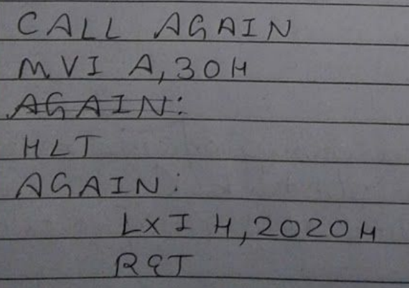
The CALL instruction is used in main program to call a subroutine and RET instruction is used at the end of the subroutine to return to the main program.
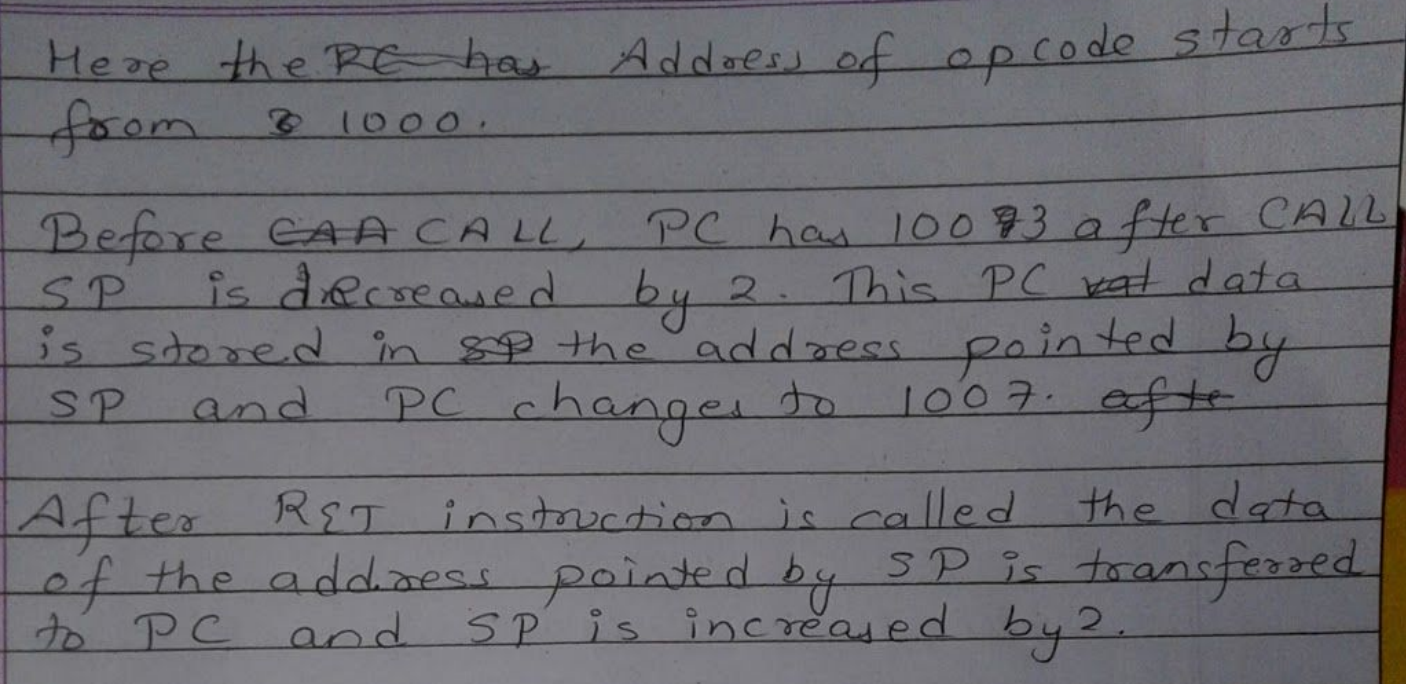
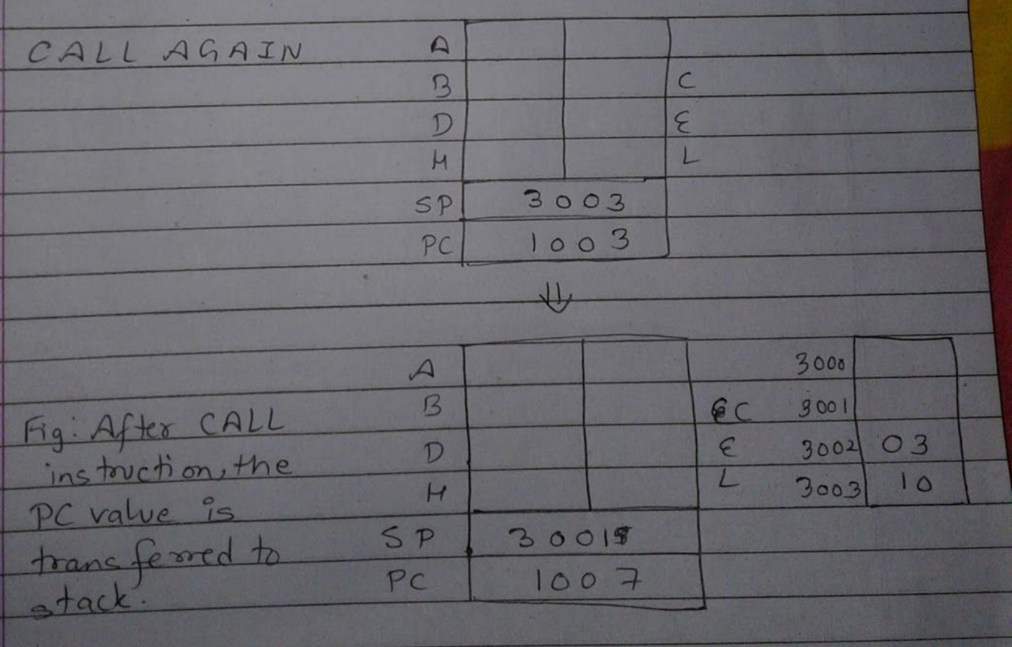
When a subroutine is called, the content of the program counter, which is the address of instruction following the CALL instruction is stored on the stack and the program execution is transferred to the subroutine address. When RET instruction is executed at the end of the subroutine the memory address stored on the stack is retrieved and the sequence is resumed in the main program.
No dedicated instruction-sheet or branching-instruction lecture is identified by the supplied chapter video titles.
9. Instruction sheet and branching
What do you mean by instruction sheet? What is the purpose of branching instructions? Explain all of them with examples. State why branching instructions are termed as most powerful instructions.
Answer
Instruction sheet
Each microprocessor can handle predefined number of instructions. The sheet, which contains all these instructions with their hex code, mnemonics, descriptions and functions is called instruction sheet.
Instruction sheet can be available in different formats with different information
The purpose of branching instruction is to goto a label or a address when called.
I Unconditional jump
JMP 16 bit address/LABEL
Used to jump when called.

II Conditional jump
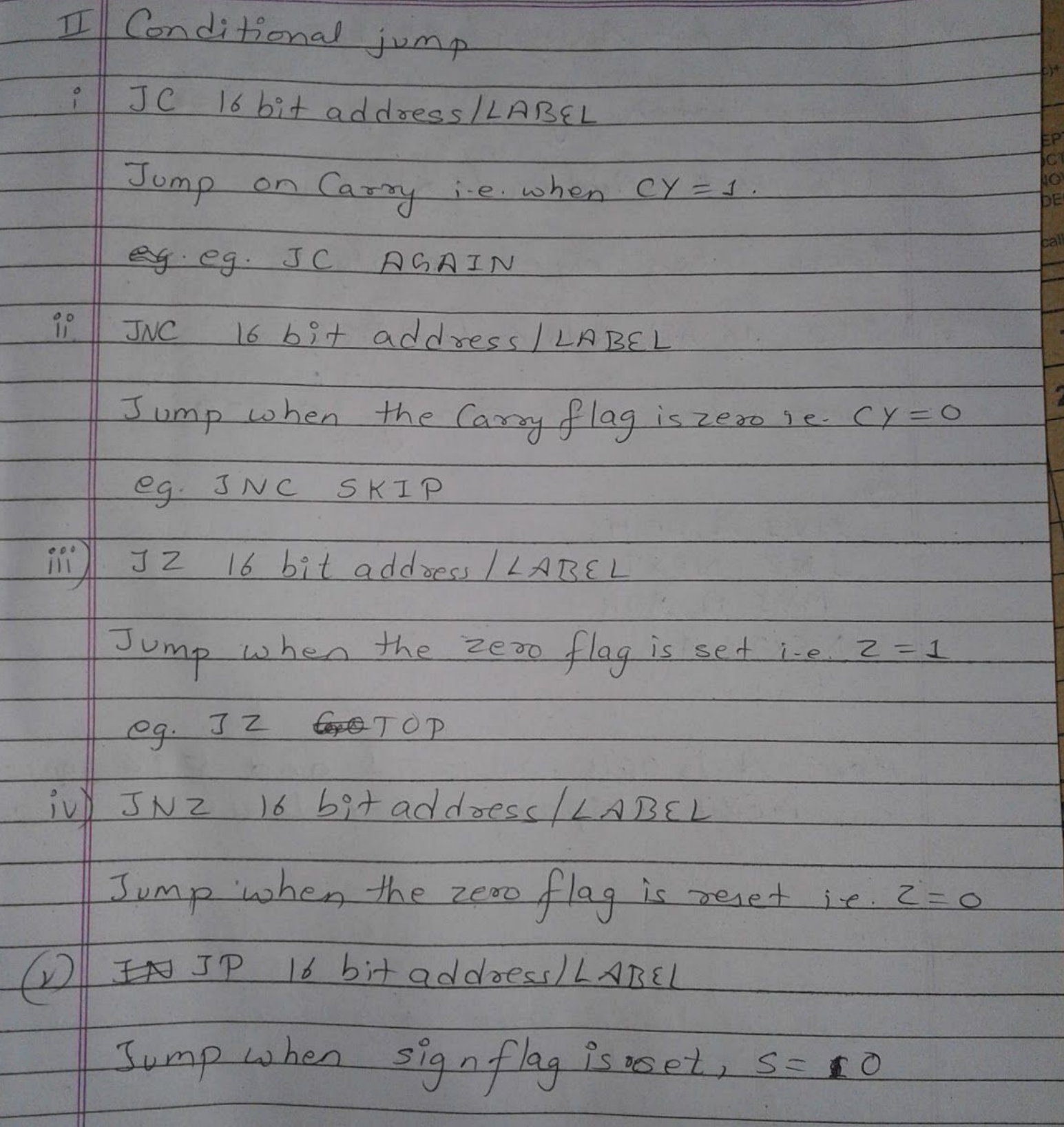
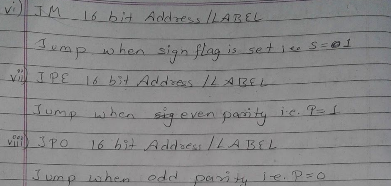
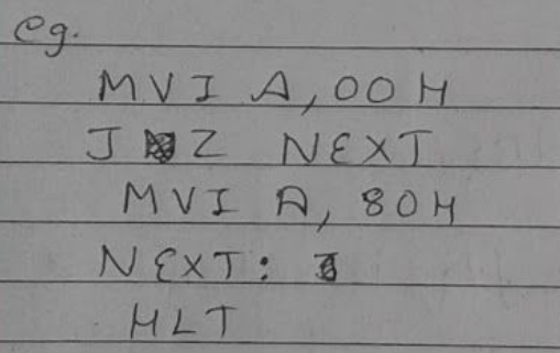
Here, A is 00H. So Z = 1 and JZ jumps to NEXT skipping other lines.
The branching instruction are termed as the most powerful instruction because these allows the microprocessor to change the program. The microprocessor is a sequential machine and it executes machine codes from one memory location to the next but branch instructions instructs the microprocessor to go to the different memory location and microprocessor continues executing machine codes from that location.
No dedicated CALL/RET versus PUSH/POP lecture is identified by the supplied chapter video titles.
10. CALL and RET versus PUSH and POP
Compare CALL and RET instruction with PUSH and POP instruction for 8085. Illustrate their usages with appropriate examples.
Answer
CALL instruction calls a subroutine unconditionally. With the instruction is called, it saves the content of the program counter (i.e. the address of next instruction) on the stack and decrements the stack pointer register by 2.
PUSH instruction also decreases the stack pointer by 2, but it saves the content of the Rₚ when called i.e the data we want to save is saved in the stack top.
The RET instruction returns the subroutine unconditionally. With this instruction, it inserts the two byte from the top of the stack into the program counter and increments stack pointer by 2.
The POP instruction when called, it also increases the stack pointer by 2 but it inserts the two byte of the top of the stack into the register pair as the data to be executed.
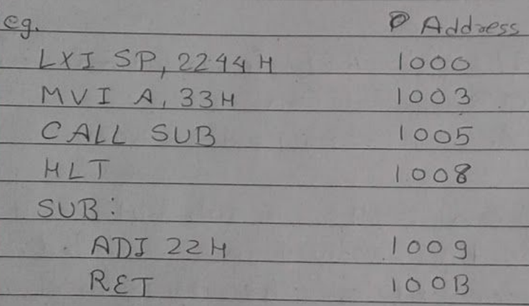
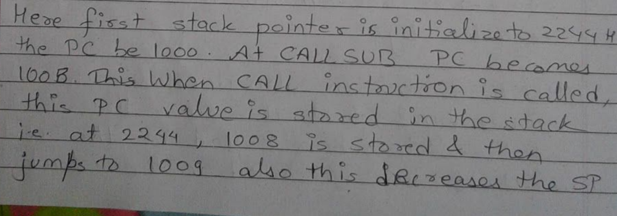

And for POP and PUSH
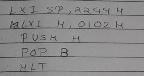
Here for PUSH and POP instruction, the PC goes in the sequential way as the microprocessor works and when PUSH instruction is called the SP decreases by 2 and the data of the Rₚ is stored in the stack. When POP instruction is called SP increases by 2 and the data of the stack is transferred to the register pair.
More videos from this chapter’s playlist
These playlist videos do not have a direct match among the questions above.
Division in Microprocessor 8085
AAkrit Subedi · 3:16
Choose a video · 5 lectures